Sine Wave Filters
Sine wave filters are becoming more & more common in motor drive applications. To understand why, we need to first look at vfd’s, why they are important, how they work, and the problems they create.

Variable Frequency Drives (VFD's)
Why VFD’s Are Important:
- VFD’s improve the efficiency of motor applications – resulting in energy savings
- VFD’s allow you to adjust the speed of electric motors to maintain constant torque load.
- They provide controlled starting and stopping of the motor
How VFD’s Work:
- VFD’s convert line current from AC to DC, then back to AC
- VFD’s control the speed of a motor by varying the output frequency delivered to the motor
- VFD’s vary the output frequency by using IGBT’s that switch at higher frequencies
Unintended Drawbacks of VFD’s:
- IGBTs create high frequency harmonics at the switching frequency of the drive.
- Harmonics can cause damage to motors requiring repair resulting in costly downtime.
- Drive output harmonics can be worse with higher fundamental frequencies and long cable lengths.
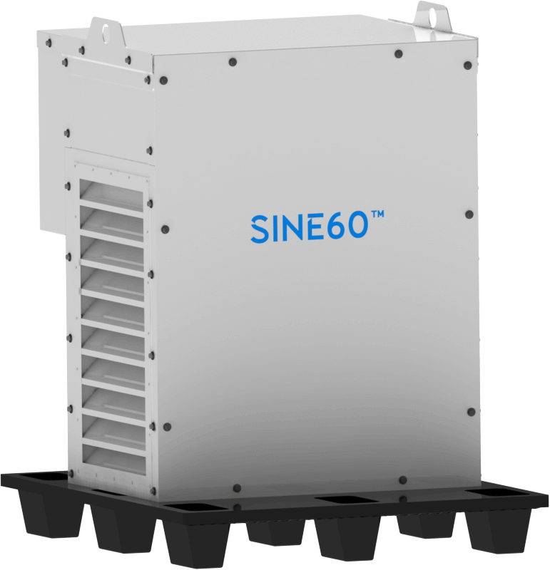
Solving Harmonics with CTM Sine Wave Filters:
CTM’s sine wave filters utilize patented inductor technology, along with highly efficient & reliable film capacitors to significantly reduce drive harmonics. The addition of a CTM sine wave filter will reduce the total harmonic distortion (THD) to less than 5%, protecting the motor, and improving system efficiency.
As the market for higher speed, higher frequency permanent magnet motors continues to increase, the need for high frequency sine wave filtering has also grown. Most magnetic suppliers attempt to solve this by oversizing traditional 60 Hz, silicon steel, sine wave filters. This results in higher cost, increased size, and reduced efficiency. CTM Magnetics has been solving high frequency problems for decades by using high frequency proprietary materials. This leads to a size and cost optimized solution that maximizes efficiency.
Running a VFD with a CTM Sine Wave Filter Solves:
Harmonic Distortion
CTM sine wave filters significantly reduce harmonic distortion, protecting motors.
High Frequency
With standard product lines ranging from 60 Hz – 500 Hz, CTM sine wave filters are designed for demanding applications.
Lower CAPEX
CTM sine wave filters offer best in class performance & reliability at low cost.